
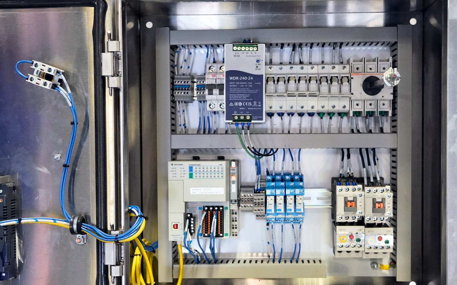
Choosing between forward and flyback is rarely a matter of finding a wattage on a chart. The decision becomes difficult when a prototype must fit a real enclosure, survive a hot cabinet, support a motor or relay surge, meet a ripple limit, and remain consistent across production lots.
That is also why familiar shortcuts fail. A 40 W supply is not automatically a flyback project. A 100 W supply is not automatically a forward project. Low ripple does not come from the topology name alone, and an industrial enclosure does not reveal what is inside it.
For an OEM team, the useful question is more practical: which architecture gives the required electrical performance with acceptable thermal, manufacturing, and qualification risk? This guide builds the answer from the application outward.
Start with the energy path, not the product label
A flyback stage stores energy in its gapped magnetic component while the primary switch is on. When the switch turns off, that energy is delivered to the secondary. The same magnetic component provides isolation and acts as the energy-storage element, allowing a relatively low component count.
A forward stage transfers energy to the secondary while the primary switch is on. A separate output inductor smooths current and continues supplying the load during the off interval. The transformer flux also needs a controlled reset path before the next switching cycle.
This distinction changes the magnetics, current waveforms, clamp or reset network, secondary hardware, control behavior, PCB layout, and the production tests that deserve attention.
| Product-level question | Flyback starting point | Forward starting point |
|---|---|---|
| Where is useful energy buffered? | Mainly in the gapped magnetic component | Mainly in the output inductor |
| When does secondary power flow? | Primarily during switch off-time | During switch on-time, with inductor freewheeling off-time |
| Typical secondary hardware | Rectifier and output capacitor | Main rectifier, freewheel path, inductor, and capacitor |
| Main magnetic control issue | Stored energy, peak current, saturation margin, leakage energy | Volt-second balance, reset margin, magnetizing current |
| Why buyers care | Lower part count and compact implementation | Smoother output-current path and greater moderate-power flexibility |
The table describes a conventional baseline. Quasi-resonant flyback, active-clamp flyback, two-switch forward, active-clamp forward, synchronous rectification, and digital control can move the boundaries considerably.
Gate 1: Define the load as a timeline
Rated power is only one point on the load profile. Record what the equipment demands during startup, normal operation, standby, communication bursts, actuator movement, charging, and fault recovery.
A supply feeding a PLC and sensors may draw a steady current with occasional relay pulses. A valve controller may have a modest average load but a high short-duration peak. A display or communication load may change in steps fast enough to expose loop and output-capacitor limitations. Two applications with the same nominal wattage can therefore need different topologies or different implementation margins.
For a flyback candidate, review peak primary current, transformer energy per cycle, current-limit tolerance, and the temperature reached during sustained heavy load. For a forward candidate, review output-inductor current, rectifier and freewheel losses, transformer reset margin, and the behavior of the clamp or reset network during transients.
Do not hide overload requirements inside a vague safety factor. State the peak current, pulse duration, repetition rate, acceptable voltage deviation, and recovery time. Those values allow a supplier to determine whether the requirement is a transient event or continuous power in disguise.

Gate 2: Translate “clean output” into test conditions
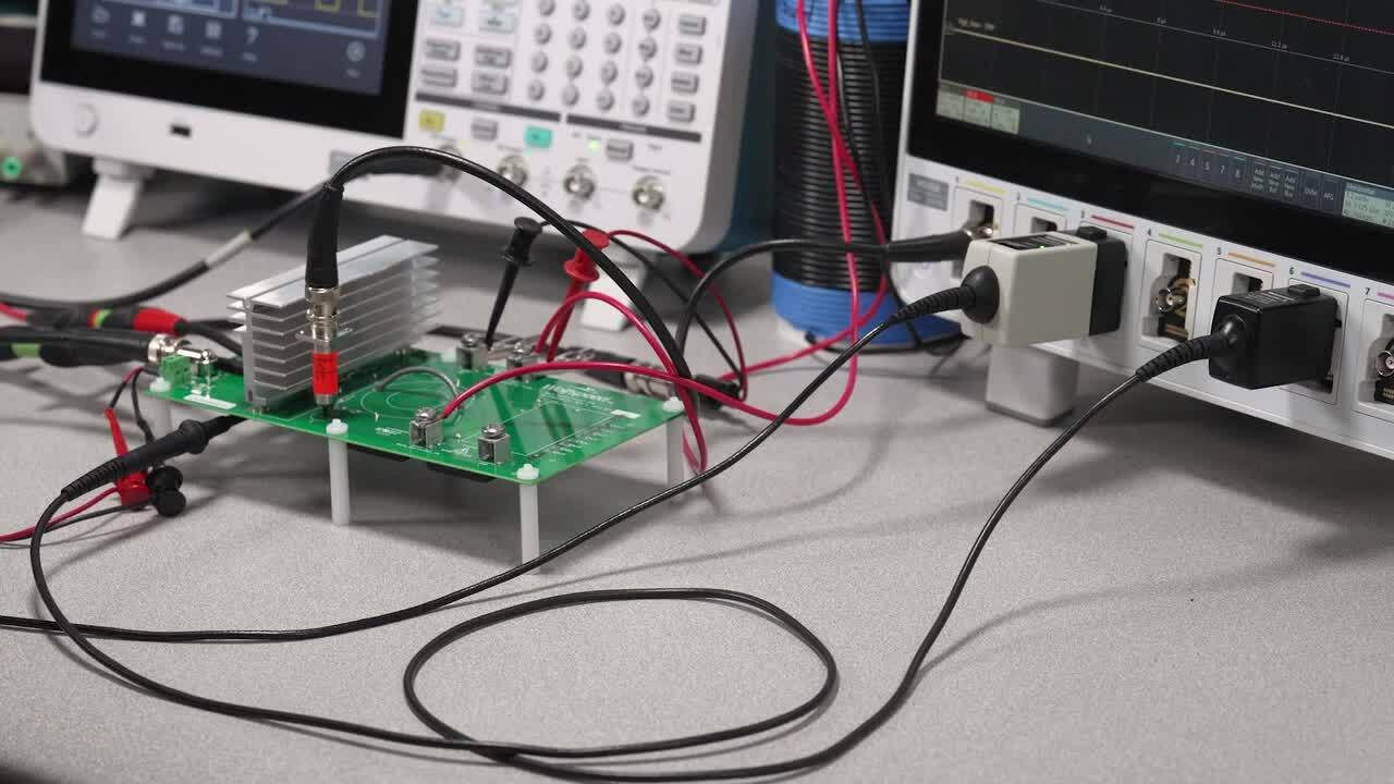
Requests for “low ripple” or “fast response” are incomplete without a measurement method. Ripple results depend on bandwidth, probe connection, output capacitance, load current, operating mode, and where the voltage is measured.
Forward converters often benefit from a continuous output-inductor current path, but that does not guarantee a quieter finished supply. Rectifier recovery, switch-node coupling, transformer capacitance, loop layout, grounding, output-capacitor impedance, and common-mode current can dominate the measured result. A well-executed flyback may outperform a poorly laid-out forward supply.
| Test | Conditions to define | Evidence to request |
|---|---|---|
| Output ripple | Input, load, bandwidth, probe connection, added capacitance | Oscilloscope capture and test setup photo |
| Load step | Current levels, edge rate, repetition rate, voltage limits | Minimum/maximum excursion and recovery time |
| Startup | Line voltage, load state, output capacitance, temperature | Monotonic rise, overshoot, delay, restart behavior |
| Brownout recovery | Drop depth, duration, repetition | Output interruption and recovery waveform |
| Short circuit | Cable resistance, fault duration, ambient | Protection mode, temperature, and recovery method |
This evidence is more useful than a topology claim on a quotation.
Gate 3: Check the thermal design in the actual enclosure
Flyback is attractive when a compact, economical isolated supply can operate with acceptable peak current and temperature. Its risk rises when continuous power, high reflected voltage, transformer loss, clamp loss, or secondary peak current leaves little thermal margin.
Forward adds parts, but the loss can be distributed across the transformer, output inductor, main rectifier, freewheel path, and switches. That can help at moderate power or high output current, provided the added magnetic and semiconductor losses are properly managed.
Neither statement answers whether the finished product survives a sealed enclosure. Compare the supply at the intended input voltage, mounting orientation, airflow, altitude, ambient temperature, and neighboring heat sources. A bench test at 25°C with the cover removed is not evidence for a control cabinet at 55°C.
For long-life projects, request temperature data for the transformer or coupled inductor, output inductor where used, primary switch, rectifiers, and electrolytic capacitors. The hottest component may change with line voltage and load. Test low line, high line, full load, and the operating point that produces the highest internal temperature.
Gate 4: Treat multi-output regulation as a load-matrix problem
Flyback can create several isolated outputs with relatively little additional hardware, which is one reason it remains useful in auxiliary and mixed-rail supplies. The difficulty is cross-regulation: the rail used for feedback may stay accurate while a lightly loaded secondary drifts.
Forward can provide a favorable starting point for higher-current outputs, but it does not make every secondary independently regulated. Winding coupling, rectifier drops, inductor arrangement, minimum load, and feedback location still matter.
Instead of asking whether a topology “supports three outputs,” provide a load matrix. Include every important combination: all rails nominal, one rail at maximum while others are light, standby conditions, startup sequencing, and faulted outputs. State the tolerance for each rail in each condition.
If the matrix cannot be met through transformer design and passive post-filtering, consider post-regulation, coupled inductors, separate DC/DC stages, or a different power architecture. This decision is often more important than the initial forward-versus-flyback choice.
Compare total product cost, not schematic part count
Flyback usually begins with fewer power components. That advantage matters in compact, cost-sensitive products, but the cheapest schematic is not always the lowest-cost product.
A design operating close to its thermal or voltage limit may require a higher-voltage MOSFET, larger transformer, more elaborate clamp, additional shielding, more output capacitance, or longer validation. A forward supply adds an output inductor and a reset or clamp arrangement, yet it may reduce the work needed to meet current ripple or sustained-load temperature targets.
| Cost area | Questions for flyback | Questions for forward |
|---|---|---|
| Magnetics | Is the gap controlled consistently? Is leakage energy manageable? | Is reset margin verified? Is the output inductor stable at temperature? |
| Semiconductors | Does MOSFET voltage include reflected voltage and overshoot? | Are switch, clamp, rectifier, and freewheel stresses documented? |
| Thermal hardware | Is extra copper, shielding, or heatsinking needed? | Does the extra magnetic hardware fit and cool properly? |
| Production | How sensitive is performance to gap, winding order, and leakage? | How sensitive is performance to reset winding, inductance, and timing? |
| Qualification | Are ripple and heavy-load temperatures close to limits? | Are startup, flux balance, and fault recovery fully tested? |
The correct comparison includes BOM, PCB area, assembly time, transformer control, yield, compliance work, and expected field returns.
Three project examples
A 30 W auxiliary supply inside industrial equipment
The load is steady, space is limited, and the outputs are 24 V plus a lightly loaded auxiliary rail. A flyback is a sensible first candidate because it can provide isolation and multiple outputs with limited hardware. The decision still depends on cross-regulation, standby consumption, enclosure temperature, and transformer consistency.
A 120 W supply for solenoids and control electronics
The system has a continuous base load plus repeated current pulses. Here the team should compare a robust flyback implementation with forward and other moderate-power architectures. The decisive tests are peak-load droop, full-load temperature, protection recovery, and lifetime at the actual duty cycle. Selecting forward only because the label says 120 W would be as weak as selecting flyback only to save components.
A 65 W measurement instrument with a strict noise limit
Low power does not make noise requirements disappear. Before changing topology, separate differential ripple from common-mode coupling and confirm the measurement method. A filtered flyback, forward converter, or another architecture may work. Layout, transformer capacitance, grounding, shielding, and downstream point-of-load regulation may decide the result.
These examples show why a universal 45 W or 60 W cutoff is misleading. Power is a screening input, not a release criterion.
Common selection myths
“Anything below 50 W should be flyback.” Low power favors flyback economics, but noise, isolation capacitance, transient response, rail accuracy, and certification can change the answer.
“A forward transformer cannot saturate.” A forward transformer does not intentionally store output energy, but incorrect reset, excessive duty cycle, startup imbalance, or timing faults can still drive the core into saturation.
“Forward always has lower MOSFET stress.” Stress depends on the exact single-switch, two-switch, or active-clamp implementation, input range, turns ratio, reset arrangement, leakage inductance, and clamp behavior.
“A 24/7 application must use forward.” Continuous operation demands thermal and lifetime evidence. Topology influences the design, but component temperature, derating, airflow, capacitor life, protection behavior, and production margin determine reliability.
“Multiple outputs require forward.” Flyback is widely used for multiple isolated rails. The real question is whether the specified load matrix and accuracy can be met.
What an OEM buyer should request
Before approving a supply, ask for information tied to the actual application:
Input range, brownout behavior, inrush current, hold-up time, and surge assumptions.
Continuous and peak output ratings with pulse duration and duty cycle.
Ripple and transient plots with documented test conditions.
Derating curves for temperature, input voltage, altitude, and mounting orientation.
Protection thresholds, timing, latch or auto-recovery behavior, and restart conditions.
Isolation rating, safety approvals, EMC evidence, and any required external components.
Critical-component temperatures at representative worst-case operating points.
Transformer and inductor production controls, approved alternates, and change-notification policy.
Sample availability, lifecycle status, lead time, MOQ, and customization limits.
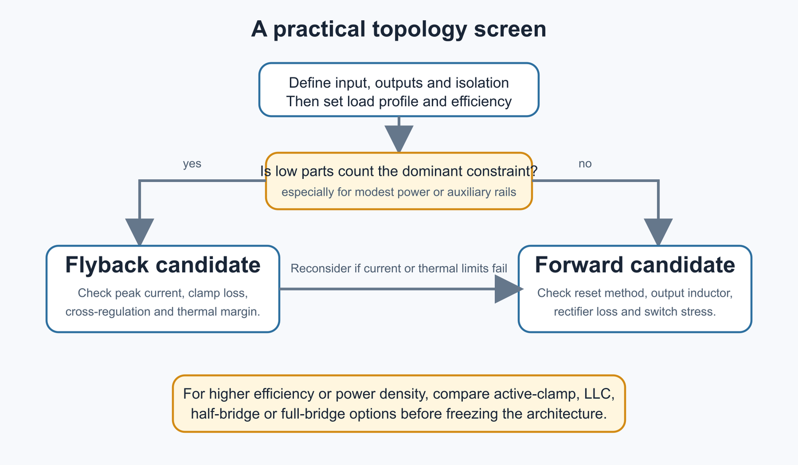
A practical decision sequence
Begin with the load timeline and electrical acceptance limits. Eliminate options that cannot meet isolation, voltage stress, transient, or thermal requirements. Compare the remaining candidates through measured loss, temperature, ripple, protection, size, and production tolerance. Only then compare total cost.
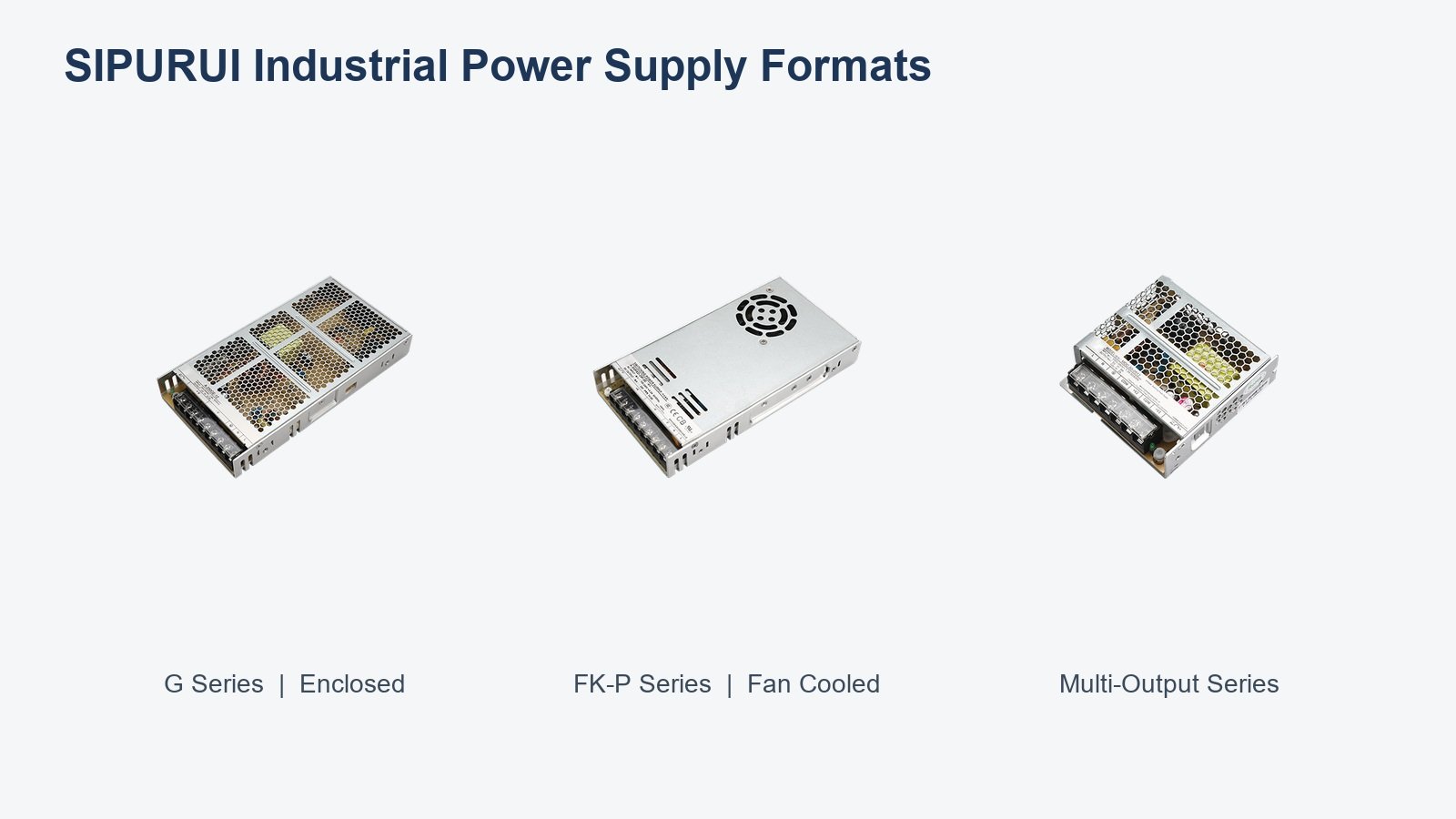
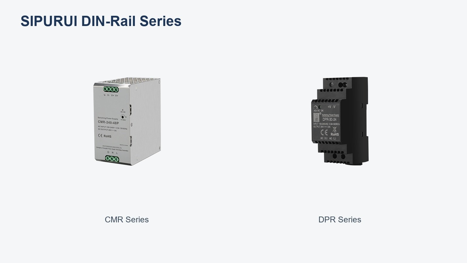
For SIPURUI industrial power-supply projects, a useful enquiry includes the input range, every output rail, continuous and peak load profile, allowable ripple, installation format, ambient temperature, cooling conditions, and target approvals. That information supports a defensible recommendation; a wattage value alone does not.